Making Contact Printing Frames
Using a vacuum frame with Kreen plastic is the most effective way to ensure positive contact between the image transparency and the polymer plate. A quick internet search will reveal many different options for comemrcially available machines. The machinery, however, can be expensive. One of the goals of this book is to reveal techniques and tools that are within the reach for the hobbyist, techniques that are also effective enough for serious artists to create high-quality work. In this section I will show you some very simple contact printing frames that I have used with great success to create high-quality photogravures with steel-backed photopolymer plates.
The Challege
The greatest challenge faced by photographers using traditional contact printing frames is maintaining even pressure between the KM73 polymer plate and the image transparency. Most contact printing frames are designed for significantly thinner material (photo paper and a negative). Toyobo’s Printight KM73 photopolymer plates are between three and ten times as thick as many photo papers. Contact printing frames made for other alternatiev photography methods either focus the pressure in the center or along the edges of the photopolymer plate. This results in poor contact away from the pressure points as well as spots created by the focused light from Newton rigns in the high pressure areas.
What are Newton Rings?
I did not know when I started learning this process, but they plagued my workflow and made spots in my prints. I realized that the smooth glass of the contact frame, when pressed against the plastic back of the image transparency, made little circular rainbows that focused and diffused light in patterns across my images. For several months I had moderate success with spraying teh back of each image transparency with clear matte acrylic. After discovering that many commercial printing plates had a slip coat to address plastic-to-plastic light refraction, I began to coat both sides of the transparency with baby powder. This helped, but did not elimnate the effects of Newton rings completely. Recallingmy time working in a conservation picture framing shop, I decided to try a piece of non-glare glass. There are two problems with glass in the picture framing world. First, it is fairly thin. Second, most of the high end glass has a UV filter. Not remembering these two details, I ended up with a frustrating week of experiments in which the exposure times were over an hour long. The experiments stopped when I accidently broke the thin glass. Finally, I sent to a story that sold windows an structural glass to order the 1/4” tempered glass that I have now. It is acid-etched on one side, much like the non-glare glass from a frame shop. The important difference is that it does not have a UV blocking film. The acid-etched side is placed against the back of the transparency. I have continued using baby powder on the transparency too, and have greatly reduced the effects of Newton rings.

Home Made Contact Printing Frame
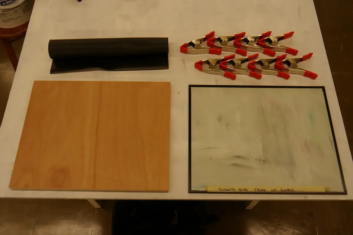
This is my old contact printing frame. You can see the four main pieces: base with thin foam pad, glass, clamps, and top frame. The base and glass are probably the two most important pices in any frame since those are the two pieces that create the pressure keeping your photographic media together during exposure. The clamps and top frame are just means of applying pressure to the base and glass in the system.
The glass is the most expensive part of this contact frame. It is 1/4” thick tempered glass that is acid-etched on one side. While thicker glass blocks a little bit of UV light (requiring longer exposure times) I like that it is less prone to distorting when pressure is applied. The acid-etched side is placed in direct contact with the back of the transparency to reduce the incidence of newton rings.
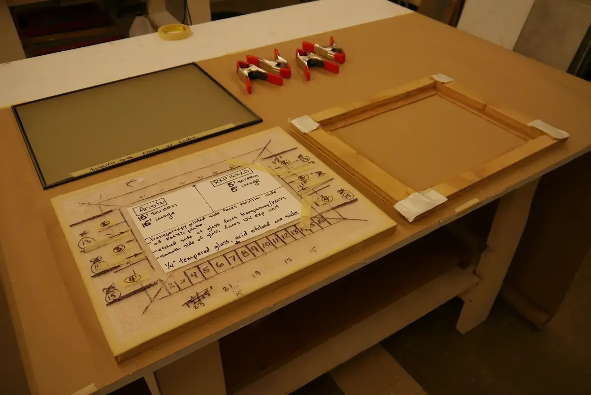
The base is 3/4” thick hardwood ply. It stays flatter than pine plywood. Medium density fiberboard (MDF) works well too. The foam pad on top of the base is very thin. I like thin shipping foam because it is inexpensive and I dont mind writing notes on it with a sharpie.
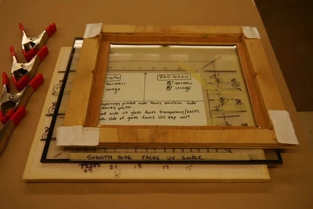
This image shows the order in which the flat pieces fit together: base, glass, top frame. They are staggered in the photo to better illustrate the order. When printing, everything will be in line and clamped together.
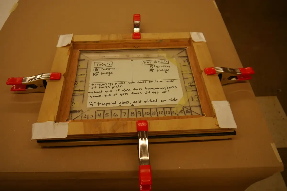
This image shows everything clamped together (without the KM73 plate or the image transparency). I only use 4 clamps with this system since the top frame helps spread the pressure more evenly. Even pressure is required for this process. To compensate for a little bit of warping in the glass and wood, I have placed two pieces of printmaking paper in the center of the system. The paper stays under the center of the polymer plate during exposure to maintain full contact over the entire surface.
The notes I have written on the paper are:
Aristo: 16’ screen 16’ image (indicates stochastic screen and image transparency exposure times.
RXP 16×20: 5’ screen 5’ image (indicates stochastic screen and image transparency exposure times.
transparency printed side faces emulsion side of KM73 plate
etched side of glass faces transparency/KM73
smooth side of glass faces UV exp unit
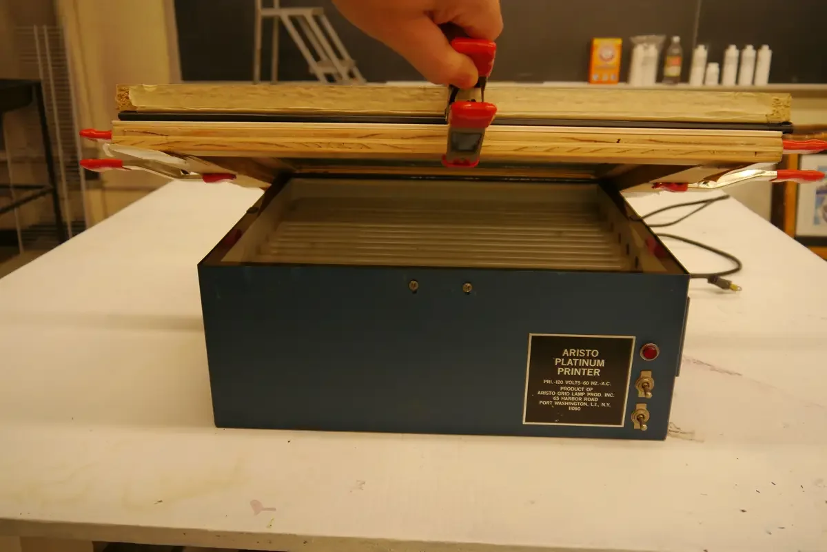
This contact frame was made to fit over the Aristo Platinum Printer. I designed it for a tight fit so taht very little light would escape, allowing me to stay in the dark room during exposure while minimizing my own exposure to UV radiation.
This UV unit has lost much of its power recently so I had to replace it with an RXP 16×20 from Ryonet. I found someone who makes new bulbs for the Aristo Platinum Printer, but it cost as much as the small Ryonet machine. Additionally, the RXP 16×20 was lighter, easier to repai, and replacement bulbs are readily available. Exposure times were different, so it took a few experiments to get the new UV unit dialed in. I think that time and initial cost will end up being more practical and less expensive to in the long run.
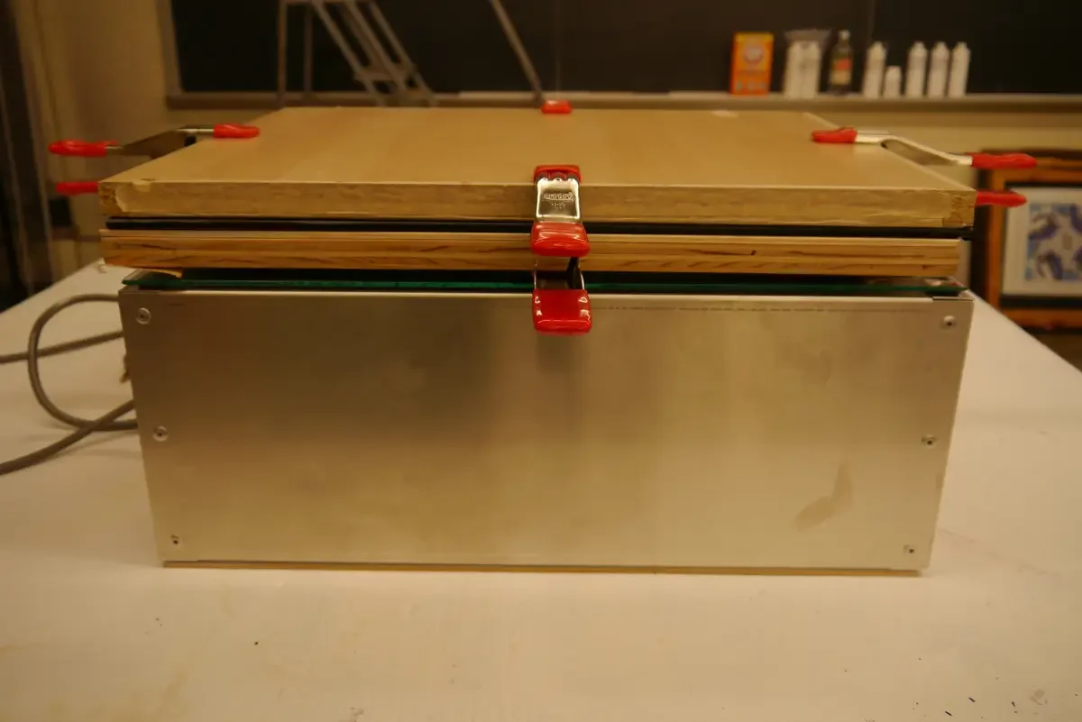
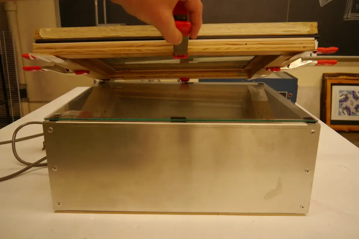
The Ryonet RXP 16×20 is larger than the Aristo Platinum Printer. You can see in this image that, while the frame rests nicely on top of the new UV unit, it does not fit over the lip. This means that more UV light will escape during exposure. To minimize my own exposure to this type of light, I cover the entire system with a thick black bag before starting the timer, and I leave the dark room immediately after starting the timer. At some point, I may make a new wood frame to fit around this UV unit.
The cost (in 2013) for the setup you see here cost about $304.
16” x 20” tempered glass (acid etched one side) 1/4” thick = $85
Ryonet RXP 16×20 UV exposure unit = $200
Two pieces of 16” x 20” hardwood plywood, 3/4” thick = $15
4 spring clamps (2” opening) = $4
I think this is the least-expensive setup that provides high quality contact printing. Shop around and see what you can find. According to their website, Toyobo KM73 plates are sensitive to UV light that ranges from 300-400 nm, but are formulated to work best at 360 nm.
https://www.toyobo-mc.jp/wordpress/wp-content/uploads/2023/09/PRT_Analog_platemaking_en.pdf
Simple Variations on the
Home Made Frame
Version 1:
This picture shows a very simple contact frame.
1 piece of 3/4” luan plywood cut to 16” x 20”
1 piece of 1/4” tempered glass, acid-etched on one side, 16” x 20”
8 steel spring clamps (2” opening)
a roll of thin foam shelf liner
Use scissors to cut the shelf liner to fit on top of the 16” x 20” piece of plywood. Place the glass on top and apply the clamps.
The glass will bend a bit. While thicker glass can minimize the distortion, it will still bend. This is why this frame uses foam shelf liner. The foam will compress under the KM73 plate, allowing more even contact.
Pay attention to the warp of the wood that you use for the base. It should be as flat as possible. You also need to keep in mind that all wood has a bias, so you will find some degree of warp in every piece. If you favor the side where the center is a bit higher than the ends, this can act to your benefit by matching the curve of the glass under clamping pressure.
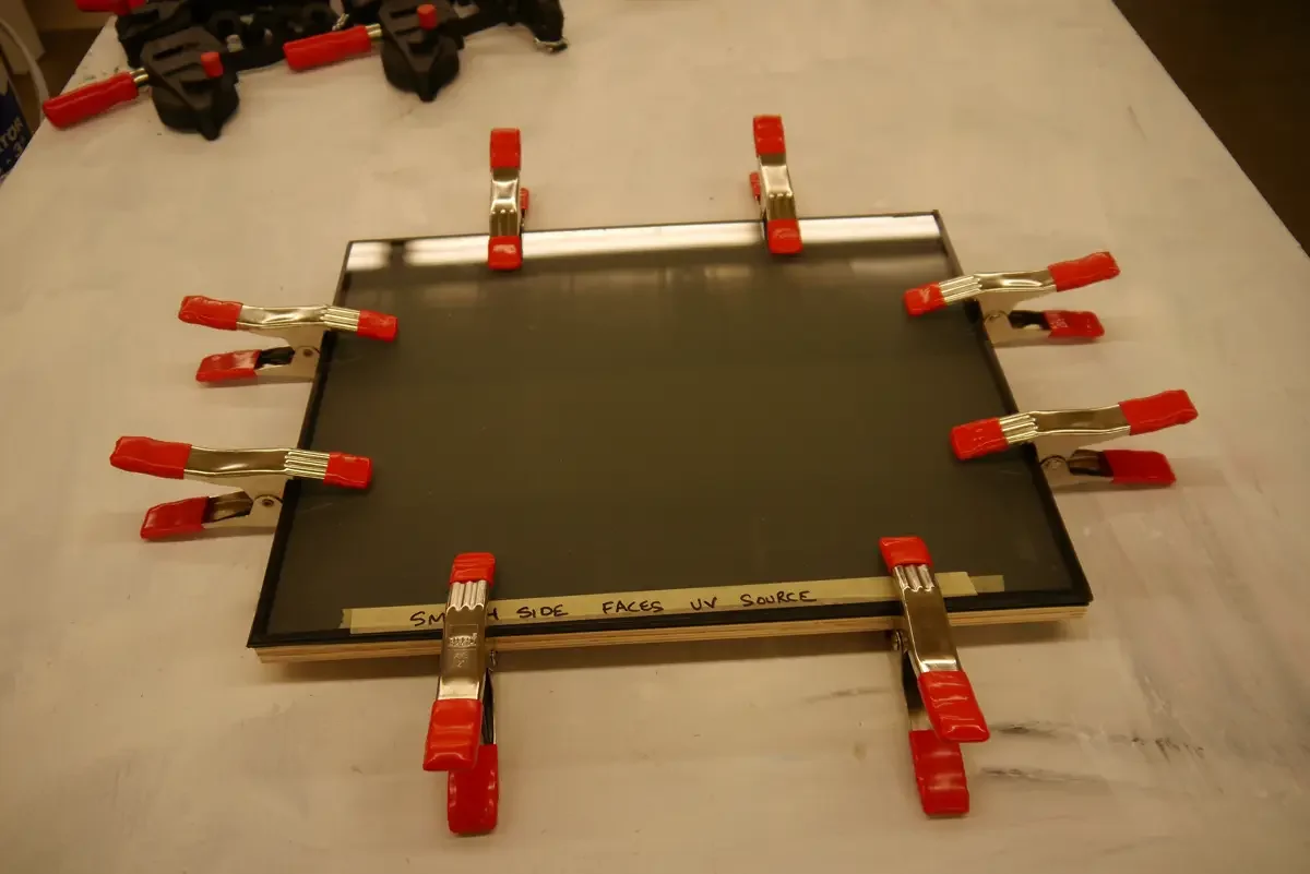
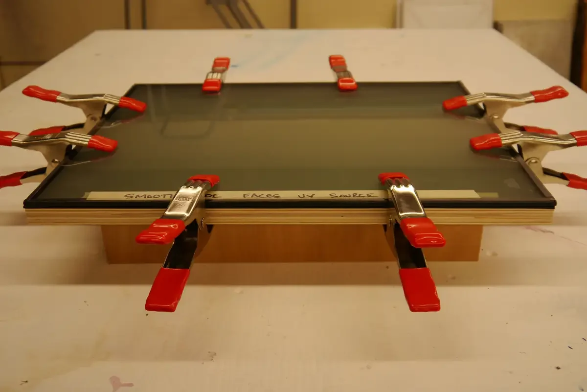
Here is a variation of the previous simple frame in which 3” stringers were added to reinforce the bottom of the 3/4” plywood. The stringers help keep the plywood flat. The added bonus is that the base is lifted 3” off the table, making clamping much easier.
Contact printing frames are designed for paper/film printing. Consider the forces acting on contact frames. Since the KM73 plates are thicker than paper (and are also backed with steel) they resist conforming to the frame as easily as paper.
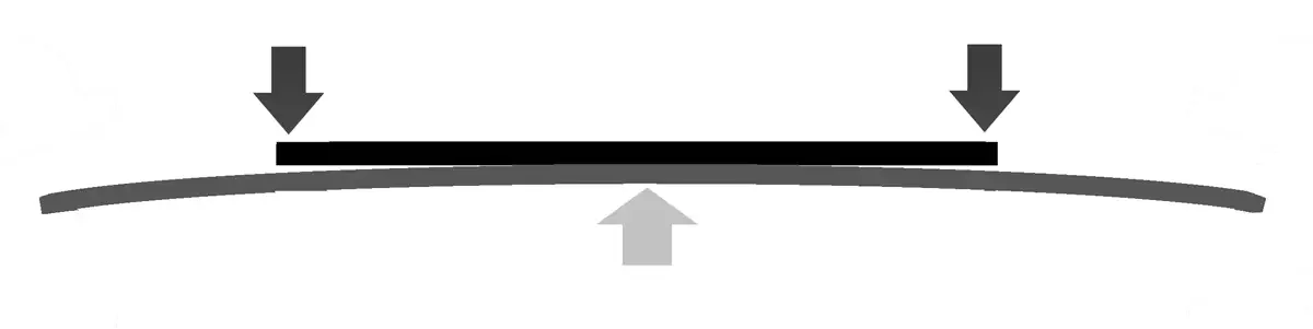
Above is an illustration of pressures found in a traditional spring-back contact printing frame that is used for most paper printing. For the process in this book, most spring-back frames don’t provide enough pressure for good contact. They are fine for paper, but not for metal-backed polymer plates.
The pressure is applied in the center of the backing by the springs, with resistance along the edges of the glass. There is some deflection to match the center pressure (which is probably why it works ok for paper printing), but the introduction of a material as thick as the KM73 plates makes for uneven pressure, leading to many light leaks between the transparency image and the polymer plate.
The next illustration shows the forces involved with a system that uses clamps around the outer edges. The top layer represents the glass. The middle represents the KM73 plate. The bottom layer represents the 3/4” plywood back.
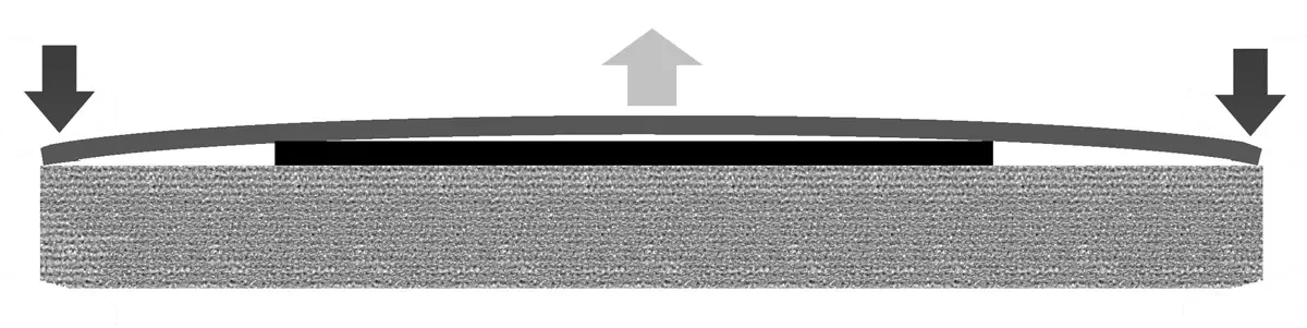
Achieving high pressure is not a problem. Add or subtract clamps around the edge to increase or decrease the pressure. The challenge is how the glass will bend. Thicker glass will minimize the bending, but it will still bend. You must either shim out the edges that surround the KM73 plate, so that the glass can meet a level surface, or you need to provide some kind of padding to allow the plate to lie in a recess.
There will be some deflections, and you will have to make some minor adjustments. Two pieces of printmaking paper (smaller than the KM73 plate) are what I have used with great success. Other suggestions have been made in this section already.
I must reitterate that nothing works better than Kreene plastic and a vacuum frame. In that system the plastic is pulled around the KM73 plate by the vacuum frame, forming even pressure across the entire surface, preventing any light leaks. If you continue making photogravures with these polymer plates, you are encouraged to look into this option. It is expensive, and in my opinion, many more important steps need to be learned before spending the money on that kind of heavy equipment.
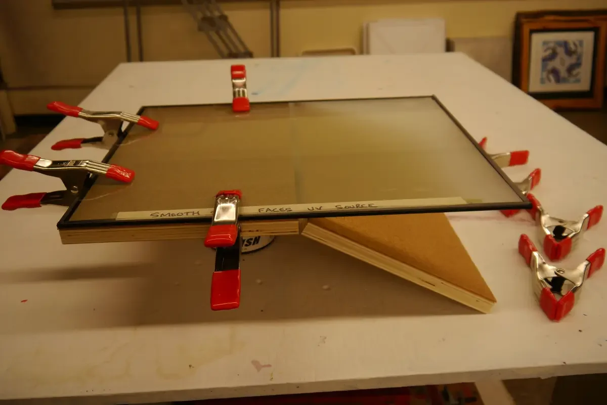
This is a split-back variation of the simple contact frame. This is a multi-use frame for different contact printing techniques. The challenge to a multi-use frame is that the padding on the 3/4” plywood cannot be as thick as it may need to be for the KM73 polymer plates. Paper, in many other printing technniques, would bend too much with thick padding, making good overall contact difficult to achieve. In this version, I have used thin cork shelf lining instead of foam shelf lining. Cork still has some flexibility, but is rigid enough for contact printing with paper.
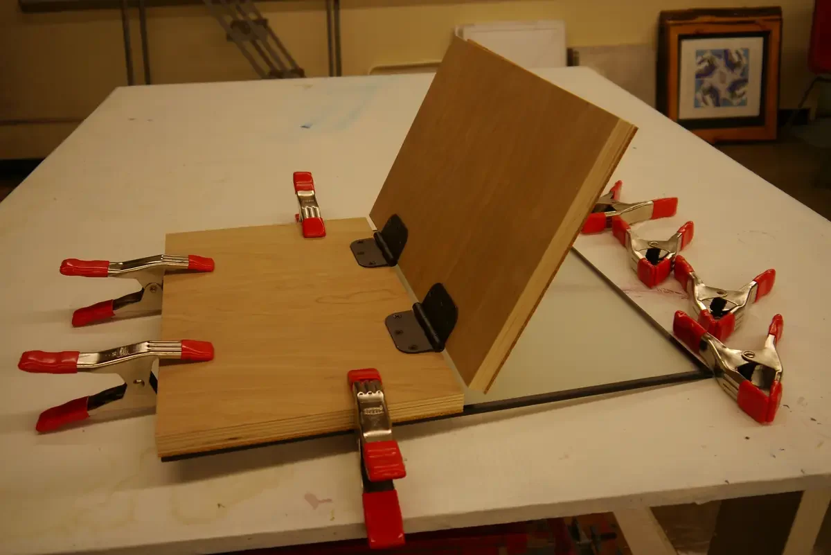
There are only two differences between the first version of this simple frame and the split-back version. The first is the use of cork instead of foam for the backing. The second is that they 3/4” plywood is cut into two pieces and joined together with hinges. This allows print-out processes to be checked mid-exposure. A split-back frame like this is not needed if you only plan to make photopolymer plates for photogravures. The option is for those who want to make a contact printing frame that can be used for multiple alternate and historical photographic processes.
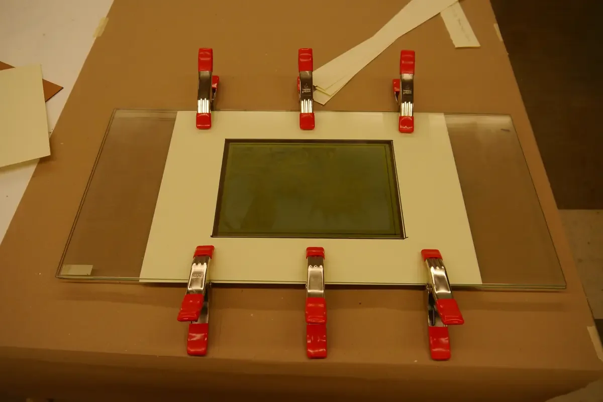
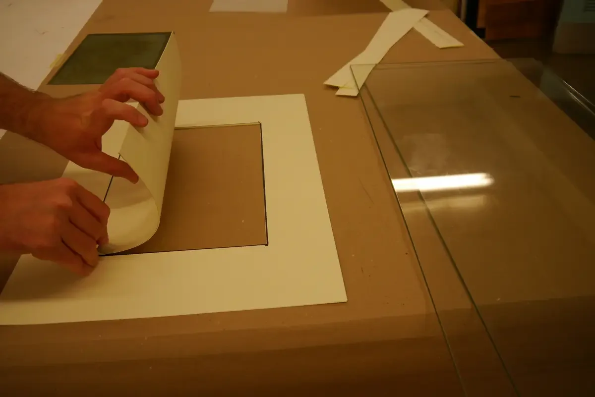
This image shows me cutting 2 pieces of Rising Stonehenge 90 lbs (250 gsm) printmaking paper so that an A4 size plate will fit in the center. The 2 pieces of paper are just barely thinner than the KM73 polymer plate. 3 pieces were a bit thicker, and may be appropriate once the transparency is added to the top of the polymer plate. These pieces act as shims, providing even distribution of pressure around the surface, allowing for good contact across the entire image area. The polymer plate sits in the cutout in the center of the paper stack.
I have only tested this inexpensive variation one time, but it seemed to work well. You do not have to cut any wood. You just need to buy tow pieces of clear tempered glass shelves from IKEA, and cut some pieces of printmaking paper to make a template for your polymer plate. This contact frame cost about $22 to make (in 2013). The pressure seems to be ok, but I think that this principle would work even better with one piece of glass on top of the 3/4” plywood backing. Cut printmaking paper is a very simple way to achieve even pressure. I imagine making templates to fit different sized plates.