Finding Image Exposure Time - Basic
The work flow involves a double exposure technique for burning an image to the KM73 plate. Both the Base Exposure Time (“screen”) and the Image Exposure Time (“image”) must be found. Frequently, the times are the same. But, going through the extra steps of finding a separate Image Exposure Time will make sure that both times are correct and the highest quality plate is made.
3 Ways to Find Image Exposure Time
Parity
Assume that the time needed for image exposure is the same as the time needed for the initial aquatint exposure. This frequently works, but it does not provide much data for troubleshooting. Since it was presented in the previous section, the parity option will not be discussed here.
Basic
Find the Base Exposure time needed to make a good aquatint matrix. Use that time to make a good aquatint on a new plate, then make variable exposures of an image to that same plate.
The first part of this section will explore the basic option, using a home made contact frame and an old Aristo Platinum Printer. Here is how the experiment was set up:
Base Exposure Time of: 13 minutes
Image Exposure times of:
Base Exposure -1= 12 minutes
Base Exposure = 13 minutes
Base Exposure +1 = 14 minutes
Base Exposure +2 = 15 minutes
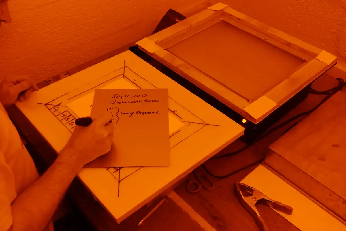
The notes I wrote on the back of the plate are:
Screen: 13’
Image: 12’, 13’, 14’, 15’
Fixxons transparency
Aristo Platinum Printer
Epson 3800
Advanced
This will be shown in the next section.
In short, it is an evolution of the Basic version, with the addition of a series of printed step wedges that provide more information.
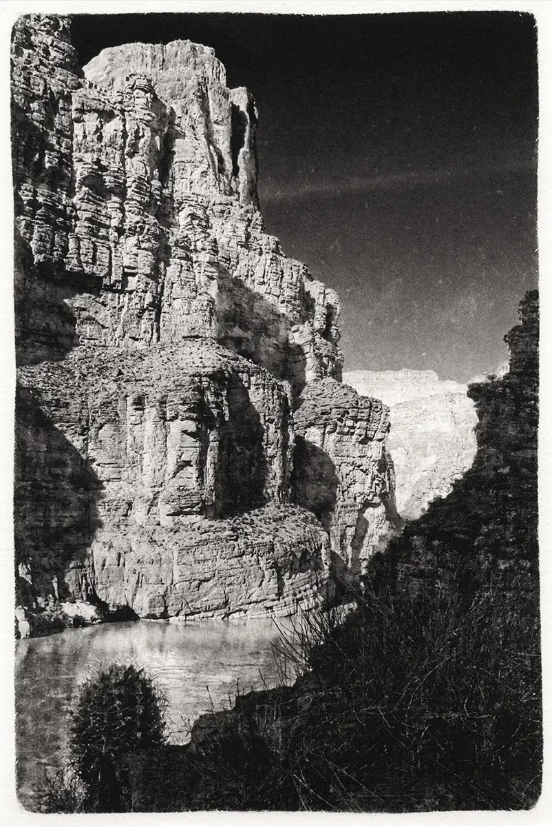
Notes on Nomenclature
“Base Exposure Time” is used to mean the same thing as “screen time”, which is just shorthand for “aquatint screen time” and “stochastic screen time” or simply “screen”.
“Image Exposure Time” is the same thing as “image time” or “transparency time”, or simply “image”.
It seems confusing. I am using these interchangeably to expose you to the varied nomenclature found in help forums, social media, and the writings of other artists. The important thing to remember is, regardless of the names, there are two distinct exposure steps: one to establish a dot pattern and another to create the image on top of that dot pattern.
Basic Option
Choose an image with enough tonal range to prive useful feedback. A digital step wedge will provide the most reliable information. Print that image with the same settings used for all other images.
The image in this example fits on an 8.5” x 11” piece of transparency. It will cover most of an A4 size KM73 plate.
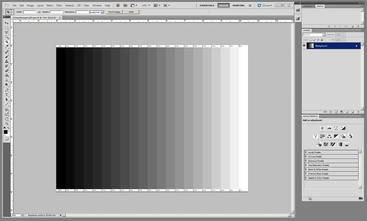
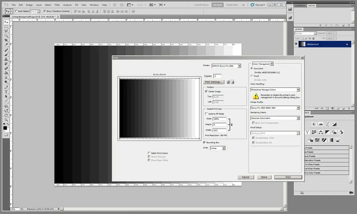
Pull up the print screen and check all of the settings to make sure they are the same as any other transparency that will be printed. Consistency is important.
Print the transparency and let it fully dry. Go through the normal process of creating a good image transparency.
Place a polymer plate on the printing frame.
Place the transparency on top of the plate.
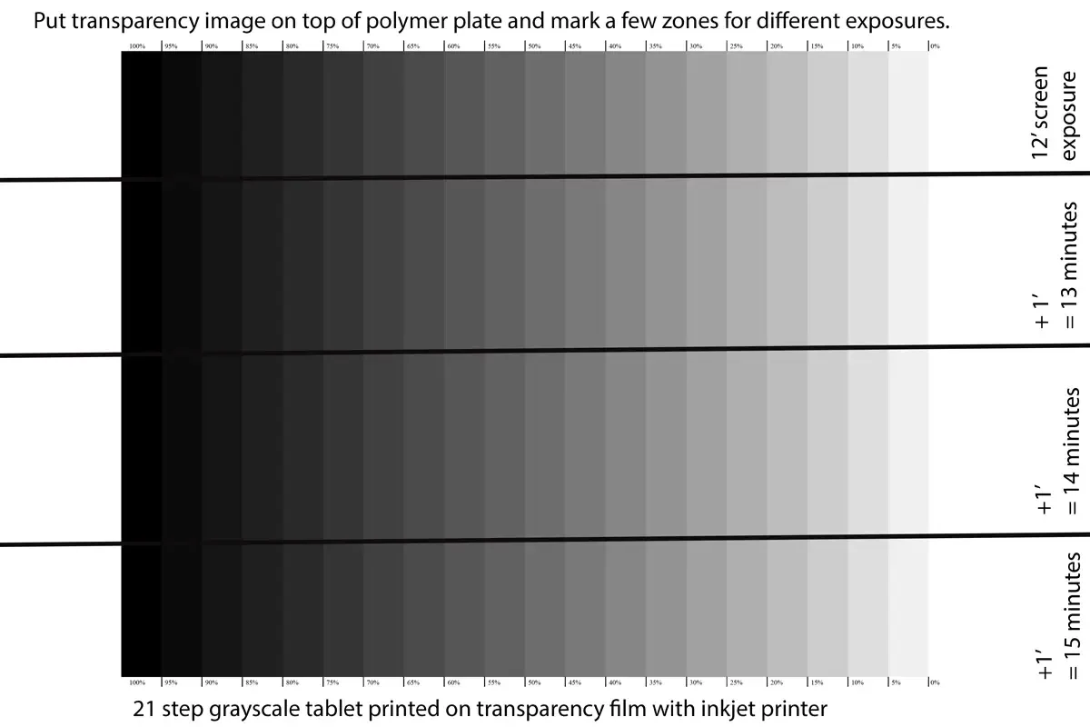
Make notes (on both the transparency and the print frame)
that will mark different exposure times for the experiment.
Remove the transparency.
Keep the polymer plate in place.
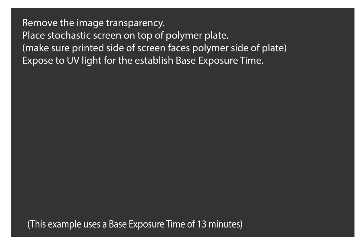
Place the stochastic screen on top of the polymer plate.
Expose the stochastic screen for the Base Exposure time.
(this example uses a Base Exposure time of 13 minutes)
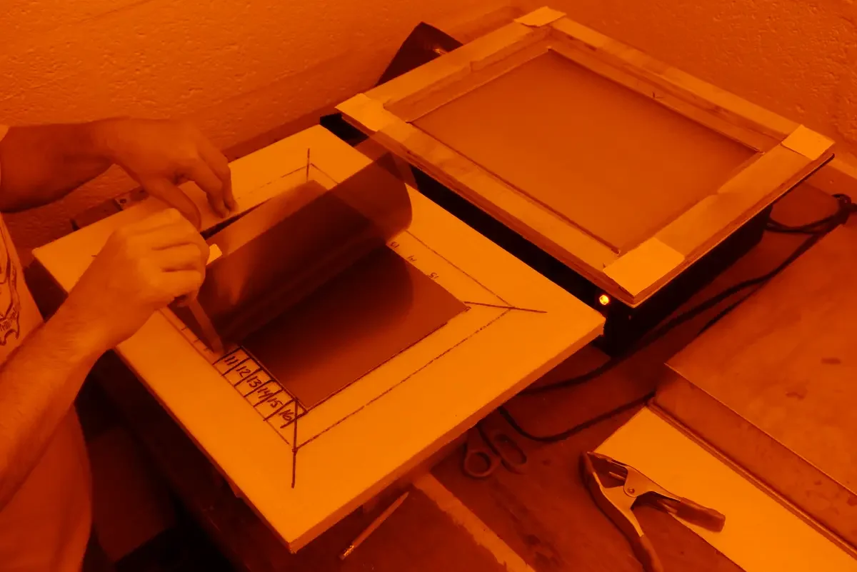
Remove the stochastic screen and replace it with the image transparency. Line up the transparency with any registration marks you may have made on the contact frame.
Tape part of the transparency so it does not move.
Make the first exposure.
Cover the first section of the transparency, and make an additional expsoure of 1 minute to the parts that are still not covered by the light-blocking plastic.

Move the light-blocking plastic down one more space, and expose again for 1 minute.

Keep moving the plastic down one more spot, repeating this process until all parts have been exposed.
Write all important information on the steel side of the KM73 plate. The most important information is the range of exposure times used in the experiment:
both the Base Exposure Time
and the different Image Exposure Times.
Other important information can include date, brand of transparency film, inkjet printer setting, UV exposure type.
Place the plate on the contact frame.
Peel off the protective film.
Place the stochastic screen against the plate, making sure that the printed side of the screen faces the polymer side of the KM73 plate.
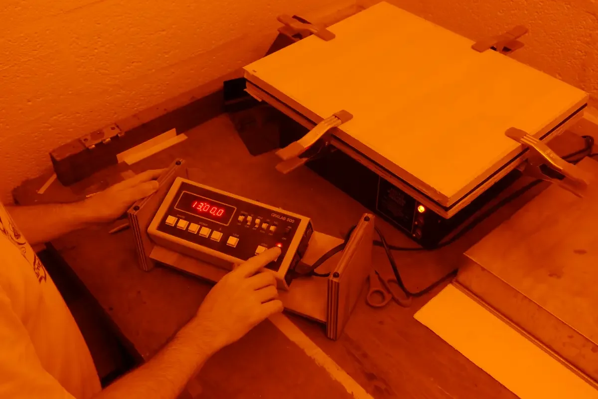
Expose the stochastic screen for the Base Exposure Time.
In this example, Base Exposure Time is 13 minutes.
After exposure, remove the stochastic screen.

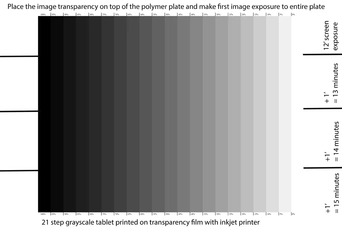
Put the image transparency (step wedge) on top of the polymer plate, making sure that the printed side of the transparency faces the polymer side of the plate.
Mark off four even spaces that indicate the planned image exposure times. Make marks on both the bed of the contact frame and on the plate itself. This redundancy can help if information is not successfully transferred to the plate or final print.
In this example, marks were made to delineate 12, 13, 14, 15 minutes.
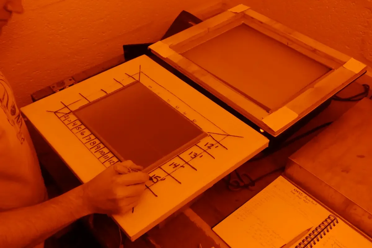
Make the first exposure to the entire image using the shortest time listed for the experiment.
In this example, the first exposure is 12 minutes.
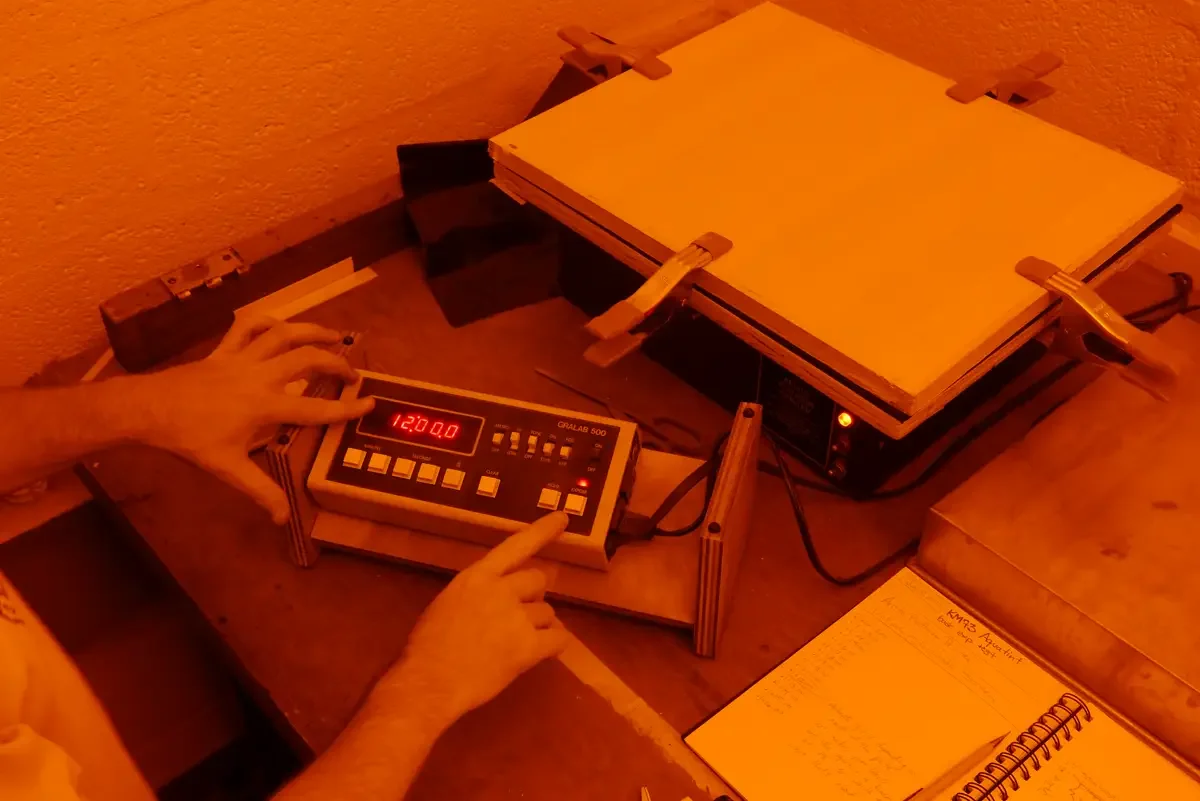
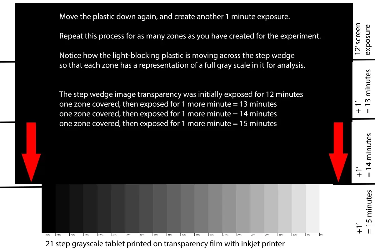
After the first exposure, remove the glass from the contact frame, but keep the image transparency against the KM73 plate (you taped one edge of it, right?).
Using a piece of thin opaque material, cover the part of the transparency and plate that was marked for the first exposure.
In this example, the opaque material is a piece of the light-proof shipping bag for the KM73 plates. The first exposure is 12 minutes, so that is the strip that is covered.
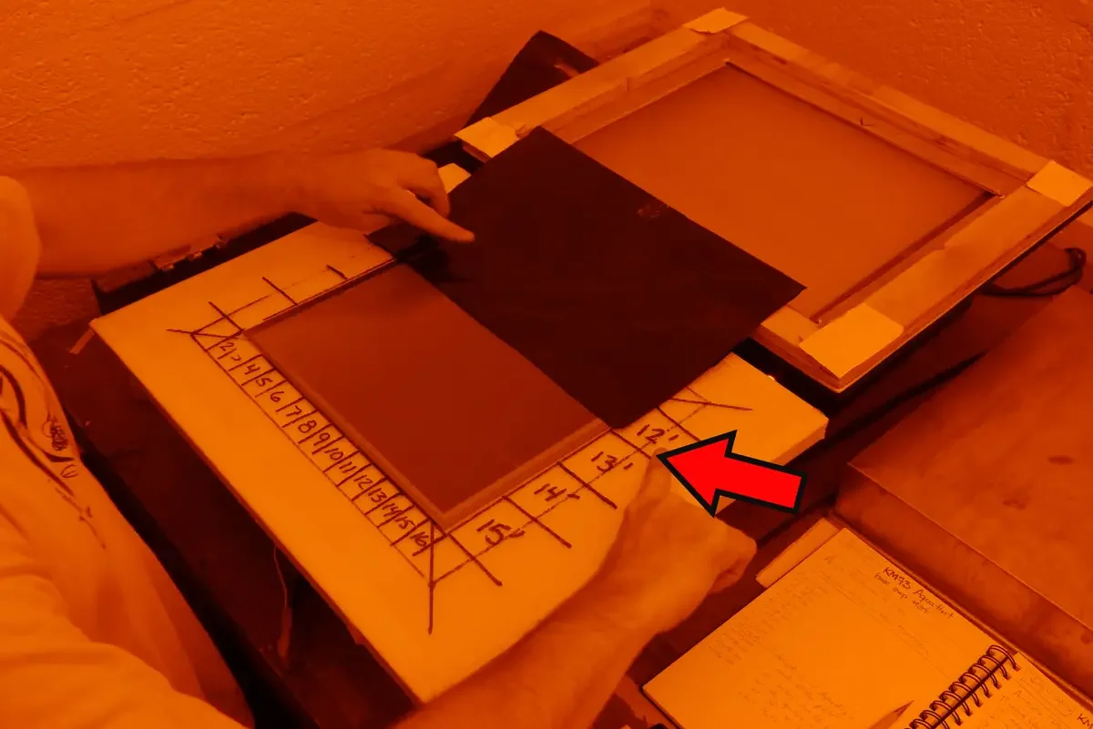
Expose the plate for enough additional time to make the second exposure.
Since the first exposure was made to the entire plate, additional exposure times are additive. Anything covered will not be exposed.
In this example, the exposure is for 1 minute.
12 minutes previous exposure.
One part covered.
1 minute additional exposure = everything uncovered will have 13’ minutes (total) exposure time.
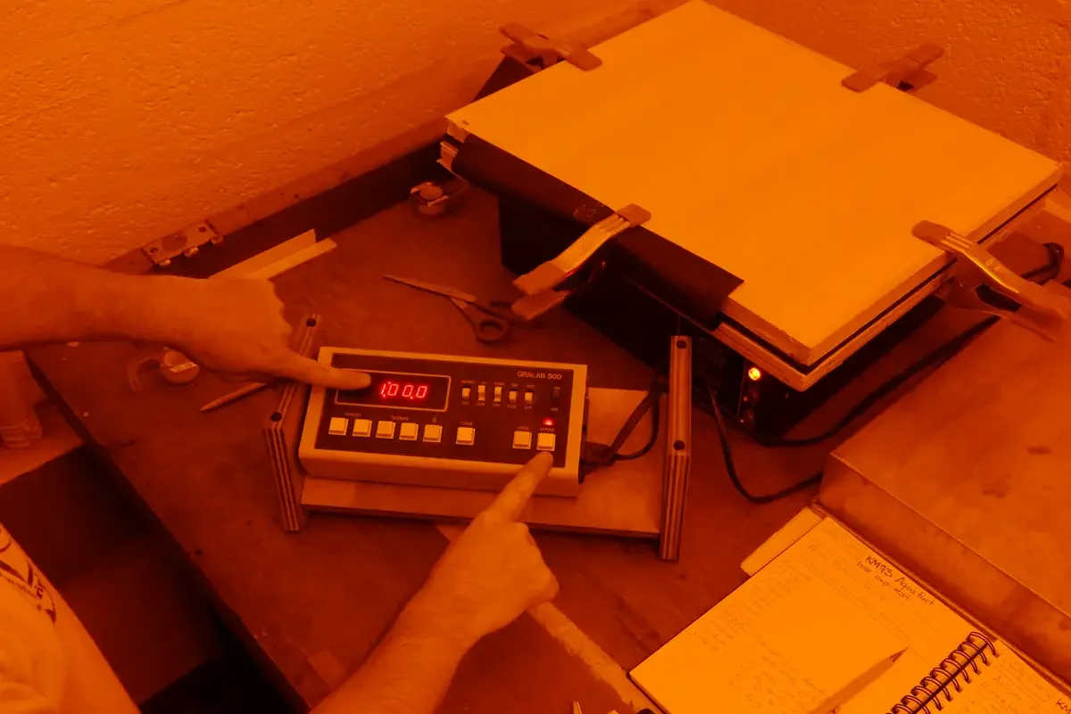
Using the marks made on the contact frame as guides,
cover sections after they received enough exposure.
In this example, the plate was exposed for 1 minute after each time the plastic bag was moved:
12 minutes initial image exposure
covered a section, plus 1 minute exposure = 13’
covered a section, plus 1 minute exposure = 14’
covered a section, plus 1 minute exposure = 15’
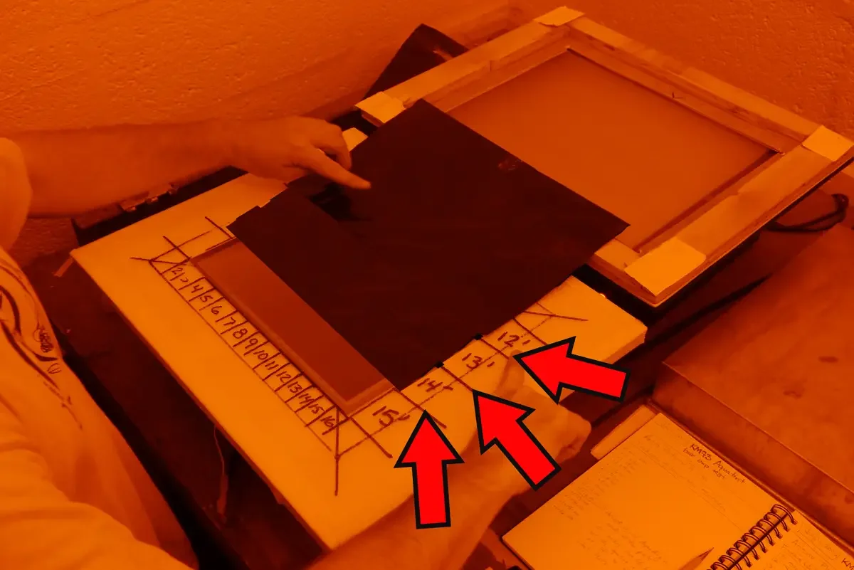
When finished with all the exposure times, bring the plate to the washout tray. Let it sit, undisturbed for 1 minute. Gentry brush the surface for 1 minute…
Go through the usual drying, curing, inking, and printing process.

Look closely at the results to find the best exposure time.
Look at both the plate and the resulting image.
Different zones on the image may look similar, but the plate will reveal inconsistencies in the aquatint matrix that might exist in different times.
Choose a time that has the best image and finest aquatint pattern. The intersection of these two things will give you the most range when you make a correction curve later.
